

Home
Harris Main PageProducts
Harris TransformersCertificates
Quality CertificatesContact
Contact Harris Company
Application
Measuring instruments, such as ammeters, voltmeters, kilowatt-hours meters, wattmeters, VAR meters and power factor meters, whether electromechanical or electronic, meet insuperable design problems if faces with the high voltages or high currents commonly used in power systems. Furthermore, the range of currents employed throughout is such that it would not be practical to manufacture instruments on a mass production scale to meet the wide variety of current ranges required. The current transformer makes it possible to measure, high currents using ordinary instruments.
Principle Of Operation
A current transformer is defined as an instrument transformer in which the secondary current is substantially proportional to the primary current (under normal conditions of operation) and differs in phase from it by an angle which is approximately zero for an appropriate direction of the connections. This highlights the accuracy requirement of the current transformer but also important is the isolating function, which means no matter what the system voltage the secondary circuit need be insulated only for a low voltage. The current transformer works on the principle of variable flux. In the ideal current transformer, secondary current would be exactly equal (when multiplied by the turns ratio) and opposite to the primary current. But, some of the primary current or the primary ampere-turns is utilized for magnetizing the core, thus leaving less than the actual primary ampere turns to be “transformed” into the secondary ampere-turns. This naturally introduces an error in the transformation. The error is classified into two-the current or ratio error and the phase error.
Accuracy Class
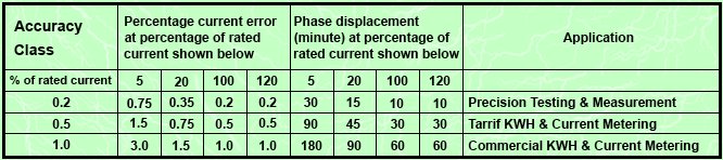
In the case of metering CTs, accuracy class is typically, 0.2,0.5,1 or 3 . This means that the errors have to be within the limits specified in the standards for that particular accuracy class. The metering CT has to be accurate from 5% to 120% of the rated primary current, at 25% and 100% of the rated burden at the specified power factor.
Accuracy class for various types of measurement are set out in IEC44-1 and VDE0414 as follows. It will be seen that the class designation is an approximate measure of the accuracy,e.g.,class 1 current transformers have ratio error within 1% of rated current. Phase difference is important when power measurements are involved, i.e., when using kilowatt-hours meters, wattmeters, VARmeters and power factor meters.
Burden
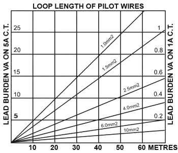
Burden is the load imposed on the secondary of the CT at rated current and is measured in VA (product of volts and amps). The accuracy class applies only to load at rated VA and below, down to one quarter VA.The burden on the secondary of a CT includes the effect of pilot leads, connections etc., as well as the instrument burden itself.The diagram shows the burden imposed on the CT due to a run of pilot wire. It will be seen that a pilot loop of 2.5 mm 2 wire, 60 meters long (30 meters distance) has a resistance of 12.5 VA on a 5 amp CT but only 0.5 VA on a 1 amp CT.
Phase Displacement
Is the angle of the phase shift between the secondary and the primary current. This angle is specified in angle minutes and positively calculated if the secondary size goes after the primary one.
Thermic Current (lth)
Thermic current is the highest primary current (effective value) that the CT can supports for 1 second, without damage, owing to excessive overloads, with secondary short circuited.
Dynamic Current (ldyn)
Dynamic current is the highest primary current (peak value) that the CT can supports for 1 second, without damage, owing electromagnetic efforts, with secondary short circuited.
Highest Voltage Limit Range
Is the standardized highest permanent permitted r.m.s. value for the phase-to-phase voltage for which a transformer is designed in respect of its insulation. It is denoted as a number which describes the voltage in KV, e.g. 0.6 meaning a highest permanent delta voltage of 850 V.
Instrument Security Factor (fs)
This typically takes a value of less than 5 or less than 10 though it could be much higher if the ratio is very low. If the factor of security of the CT is 5, it means that the composite error of the metering CT at 5 times the rated primary current is equal to or greater than 10%. This means that heavy currents on the primary are not passed on to the secondary circuit and instruments are therefore protected. In the case of double ratio CTs, FS is applicable for the lowest ratio only.
Knee Point Voltage
That point on the magnetizing curve where an increase of 10% in the flux density (voltage) causes an increase of 50% in the magnetizing force (current).
Open-Circuit-Voltage
The outputs of current transformers are constant current sources. If the burden is increased the output voltage simultaneously increases too (according to the relation U=R.I) as long as magnetic saturation occures. Above the saturation the peak voltage increases while the deformation of the secondary current is growing until the maximum at an almost infinitely high load (that means open secondary circuit).
Thus high voltage spikes may occure which can be dangerous to human beings and which can damage the CT. There are configurations of CT which are protected against damaging because they have a higher insulation of the winding. But that does not mean, that the open-circuit-operation is harmless to human beings. Consequently an open-circuit-operation is to be avoided. Unloaded CTs have to be short-circuited secondarily.
Harris Measuring Current Transformer
This compact range of current transformers is designed to comply with IEC 44-1 and VDE 0414 regulations. The units are clean and uniform in appearance and are entirely enclosed in impact and heat resisting housings. The moulded apertures allow the transformers to be rapidly and firmly clamped or wedged to metric or inch busbars. Alternatively, transformers can be supplied with mounting feet. All terminal fittings are manufactured from plated brass and are grooved to ensure excellent contact pressure. Current transformers are available in accuracy classes ranging from 0.2 to 3 and are fully tested using modern and highly accurate test equipment prior to despatch. Test certificates are available on request.
Harris Protection Current Transformer
Protective current transformers are designed to measure the actual currents in power systems and to produce proportional currents in their secondary windings which are isolated from the main power circuit. These replica currents are used as inputs to protective relays which will automatically isolate part of a power circuit in the event of an abnormal or fault condition therein, yet permit other parts of the plant to continue in operation.
Satisfactory operation of protective relays can depend on accurate representation of currents ranging from small leakage currents to very high overcurrents, requiring the protective current transformer to be linear, and therefore below magnetic saturation, at values up to perhaps 20 times full load current. This wide operating range means that protective current transformers require to be constructed with larger cross-sections resulting in heavier cores than equivalent current transformers used for measuring duties only. For space and economy reasons, equipment designers should however avoid over-specifying protective current transformers. Harris technical staff are always prepared to assist in specifying protective CT’s but require some or all of the following information:
(a) Ratio (b) Accuracy class (c) Burden or pilot wire resistance, or length of run and pilot wire used (d) Primary conductor diameter or busbar dimensions (e) System voltage level
This compact range of protection current transformers is designed to comply with IEC 44-1 and VDE 0414 regulations and to follow international trends in control gear/switchgear design. Protection current transformers are available in 5P or 10P accuracy classes for each transformer ratio thereby enabling the designer to select a transformer suitable for applications ranging from magnetic trips or thermal overload relays to IDMT overcurrent or earth fault relays.
The units are clean and uniform in appearance and are entirely enclosed in impact and heat resisting housings. The moulded apertures allow the transformers to be rapidly and firmly clamped or wedges to metric or inch busbars. Alternatively, transformers can be supplied with mounting feet. All terminal fixings are manufactured from nickel plated brass and are grooved to ensure excellent contact pressure.
Accuary Class
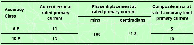
Accuracy classes are defined as 5P or 10P with limits according to the following table extracted from IEC 60044-1.
Composite Error
The rms value of the difference between the instantaneous primary current and the instantaneous secondary current multiplied by the turns ratio, under steady state conditions.
Accuracy Limit Factor
The value of primary current upto which the CT complies with composite error requirements. This is typically 5,10 or 15,which means that the composite error of the CT has to be within specified limits at 5, 10 or 15 times the rated primary current.
Features
* Conform to IEC 44-1 and VDE 0414
* Clean, uniform appearance
* Rapidly fitted to metric or inch busbars
* All transformers are fully tested using modern and highly accurate test equipment prior to despatch
* Test certificates available on request
* All standard primary current ranges available
* Totally enclosed in tough, self extinguishing mouldings
* Available in accuracy classes to suit application